The two missing components for the Active Fuse Tester arrived today. This allowed me to create KiCad symbols and footprints by direct measurement. I had searched for the datasheets, but came up with no matches. I even asked the eBay seller, but they stated that they were ‘only retailers’ and the ‘even our supplier doesn’t have any datasheets’.
No matter. It’s not that difficult to create symbols and footprints. There are plenty of tutorials online, particurly on YouTube. I recommend the Getting To Blinky 4.0 set of tutorials by Chris Gammell of Contextual Electronics. It gave me a very good foundation when I started using KiCad.
The Active Fuse tester is one of my educational circuits for the after-school club I will be involved in come the September term. The idea is that the circuit will demonstrate how Transistors can be used as switches and the project will be a useful thing to have on a workshop/lab bench.

Active Fuse Tester v1.01
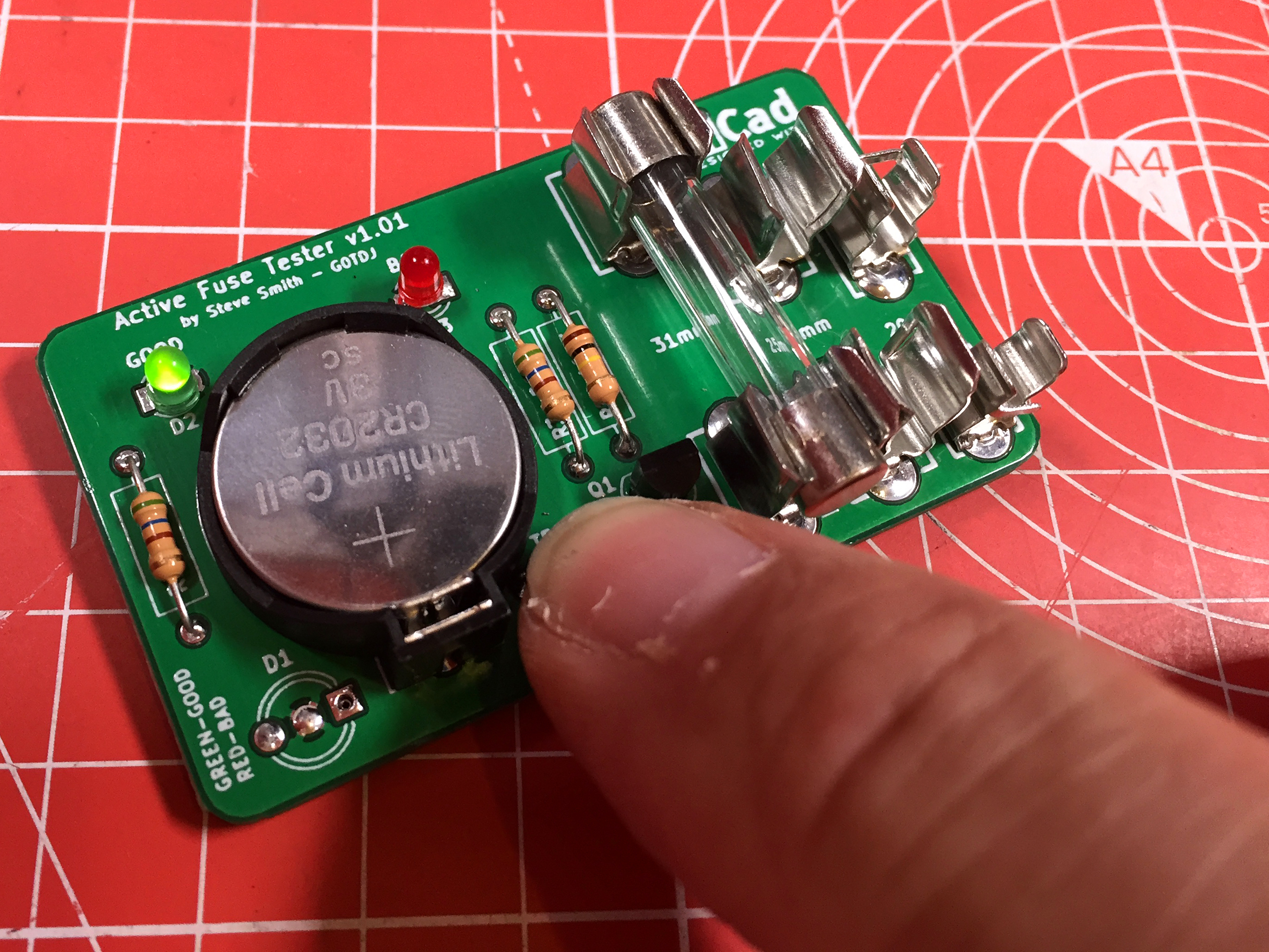
The small PCB holds a 3V CR2032 type battery and a few other components, as well as fuse clips in three different sizes. I wanted the board to be as useful as possible so it can test 31mm, 25mm (House Fuses) and the small 20mm types.
I included the option of using either two LEDs, one Red one Green or a single BiColour LED to indicate the state of the fuse under test. A single 2N3906 PNP transistor is either switched on or off when the test switch is pressed leading the appropriate LED to light. The one-piece fuse holders and the extra connections have been removed so the circuit looks slightly different now.
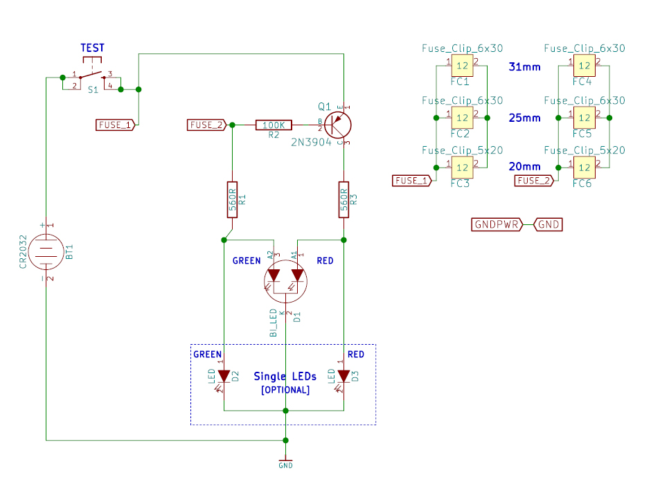
Active Fuse Tester v1.01 Schematic
I also had to add the link for GND to GNDPWR which I think is just a KiCad curiousity. Otherwise, the GND copper pour doesn’t work correctly. I’m sure there is another way to prevent the need for this but it only takes a rew moments to draw.
The boards have been ordered and design files will be available in the educational section once proved to be correctly working.
[UPDATE: 30th August 2018]
Having built a couple of the boards, I discovered that I had got the fuse clip distances wrong and the transistor marked on the PCB and Schematic is incorrect. It requires a 2N3906 PNP (Not a 2N3904 as marked). I have corrected the text above to reflect this.
Active Fuse Tester v1.01
The circuit works fine with both the single BiColour LED or two single LEDs. I have also tried a BC547 and that seems OK too, provided you fit it backwards to the silk screen marking.
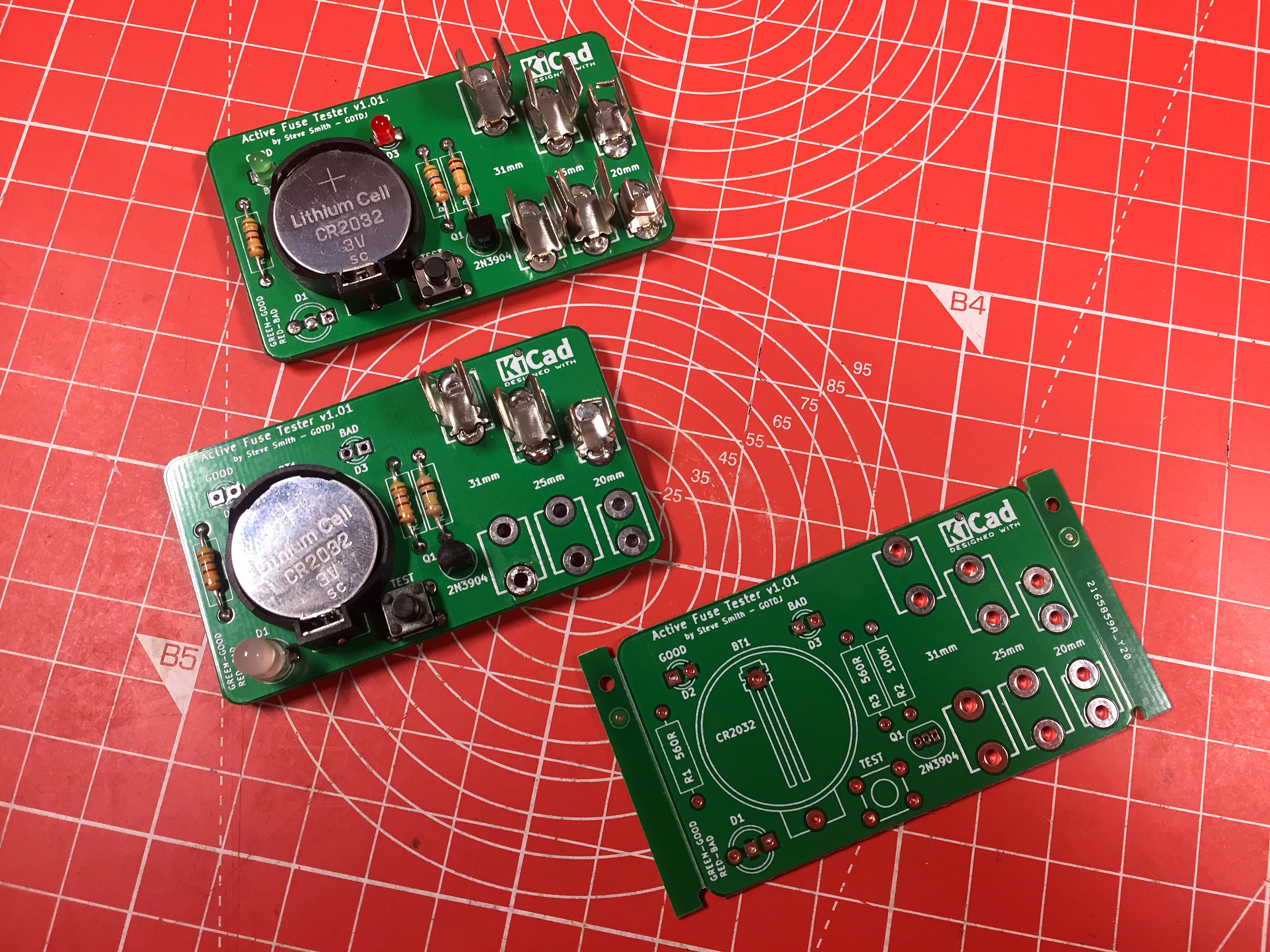
Active Fuse Tester v1.01 Versions
Upon building the second board, I left out half of the fuse clips since it is easy to press the fuse under test on to the bare connections. The next itteration of the board will include a full set of correctly spaced clips.

Active Fuse Tester v1.02
I have moved the battery onto the rear to give the board a smaller footprint using an SMD clip type. I also moved the BiColour LED to the top edge of the board between the two singles.
Now having correctly spaced the fuse clip footprints, the new board is good to go. They have now been ordered and are in production.