Simple 555 LED Flasher v1.00
It is my privilege to help out at a local school, here in the UK, teaching students Radio with a view to them gaining radio licences. I am very pleased to have been asked to help out with an additional session for electronics, starting in September. With this in mind, I have been putting together a few simple circuits for the students to practice on. The first of which is a simple 555 LED Flasher.

Simple 555 LED Flasher v1.00
The switch in the top left is optional and the connection can be bridged by a small wire, perhaps saved from soldering one of the resistors. Being an educational board, I deliberately left the component values on the silk screen to enable building without any other documentation required.
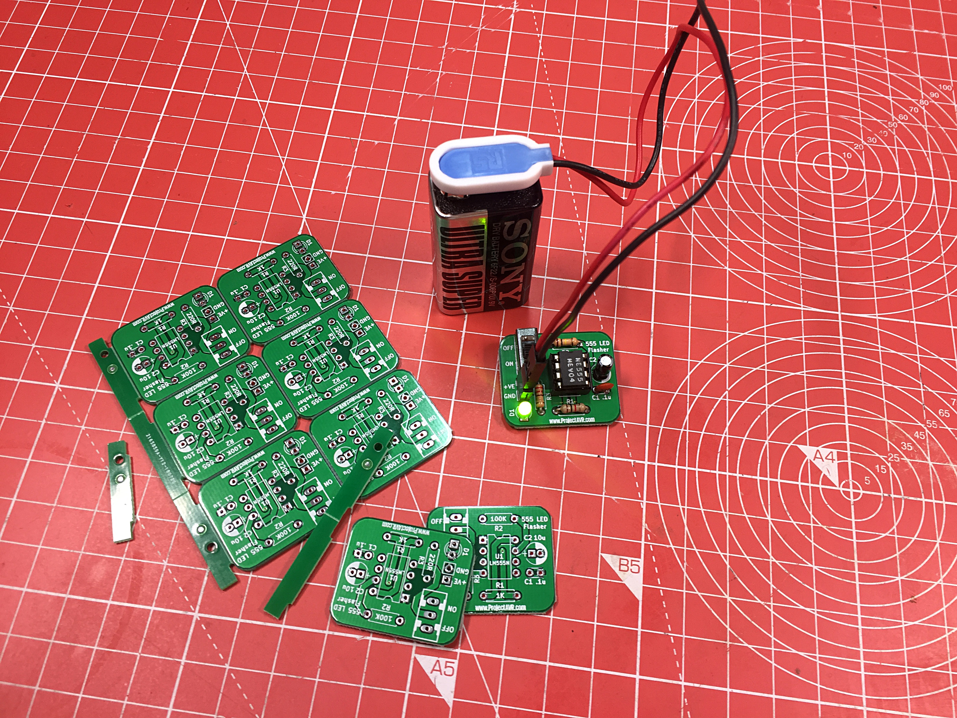
Simple 555 LED Flasher and Panelised PCBs
In the above image, you can see a working board aside the panelised PCBs that it was taken from. It takes around 30 minutes to build carefully. It is hoped that these will allow students to get to grips with soldering and be able to take a working circuit away from the session.
Here are all the files for fabricating the Simple 555 LED Flasher v1.00:
- Simple 555 LED Flasher v1.00 KiCad (v5.00) files .ZIP
- Simple 555 LED Flasher v1.00 Gerbers .ZIP file
- Simple 555 LED Flasher v1.00 Schematic .PDF file
- Simple 555 LED Flasher v1.00 Images .ZIP file
- Simple 555 LED Flasher v1.00 BOM .TXT File [To Follow]
Active Fuse Tester v1.02
This project is intended to demonstrate the way a transistor can be used as a switch, as well as being a useful piece of test equimpment to have on the bench.
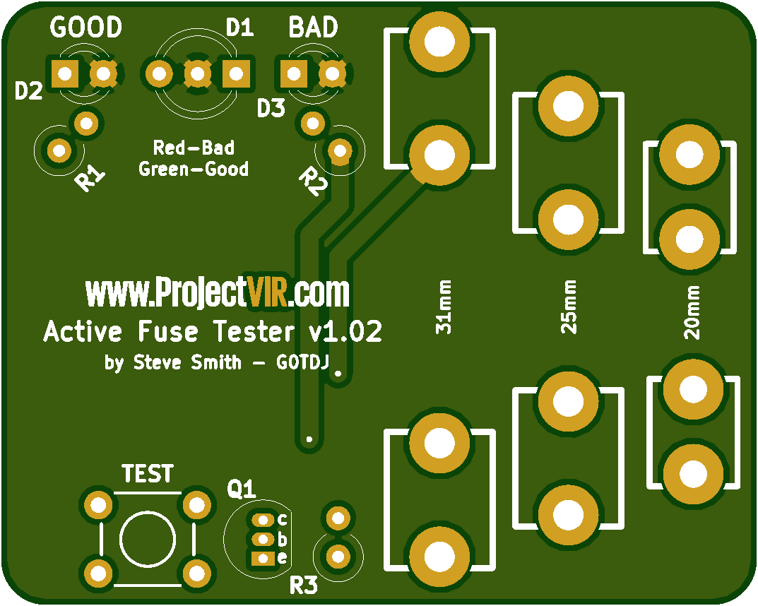
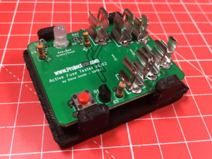
Active Fuse Tester v1.02
The board accomodates three different sizes of fuse and is intended to be used bare (Hence no mounting holes). My own personal board has stick on feet in the corners of the board near the fuse holders and stands on those and the battery holder on the rear (I have since designed a simple 3D Printed base, see later).
Construction is almost trivial. The only ‘Gotcha’ is fitting the BiColour LED reversed so that good fuses are indicated by red and bad by green. If this happens, it is a simple case of desoldering and resoldering the component the other way around. No harm will come to the LED since it’s common pin is in the center.
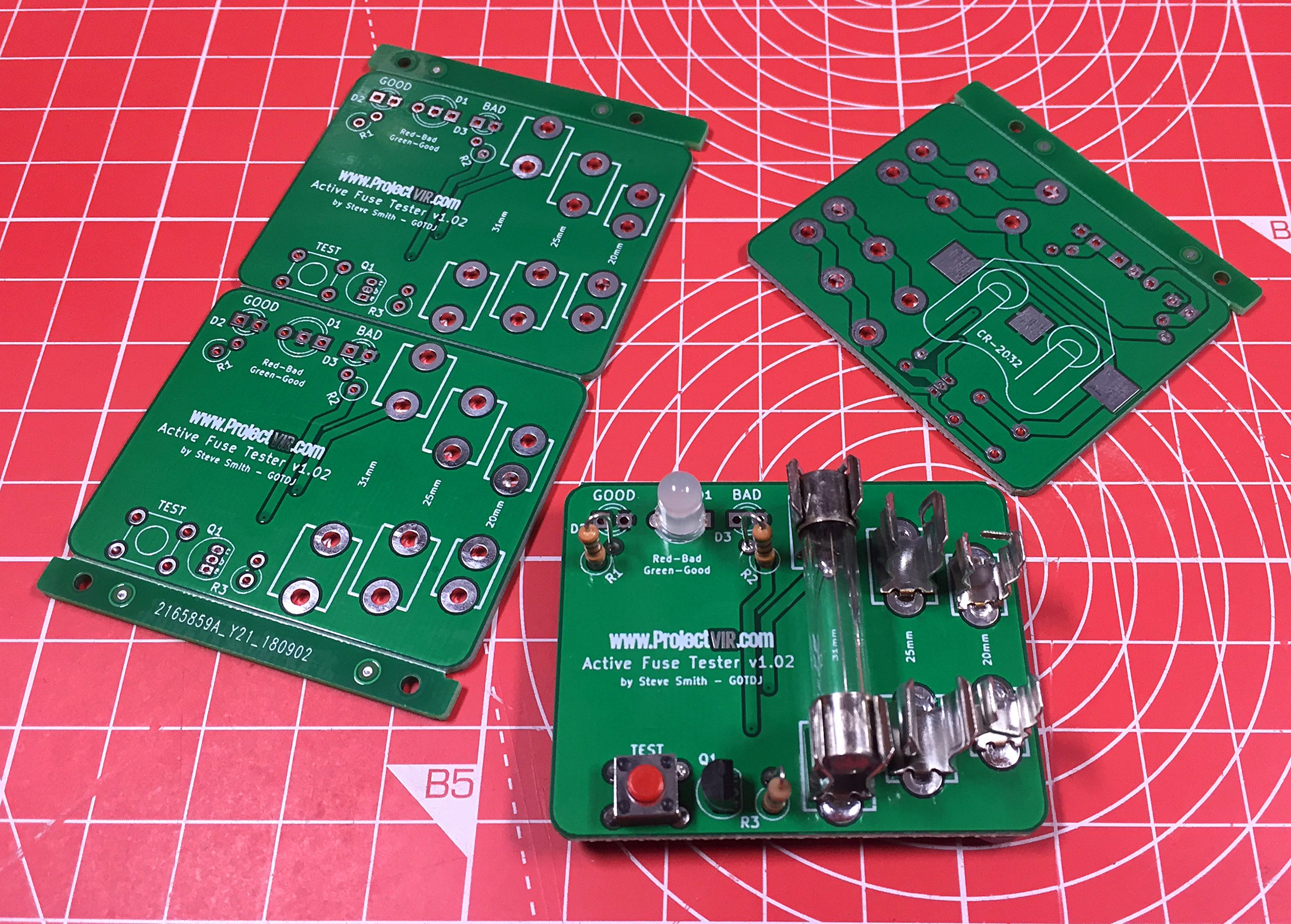
Active Fuse Tester v1.02 PCBs
Here are all the files for fabricating the Active Fuse Tester v1.02:
- Active Fuse Tester v1.02 KiCad (v5.00) files .ZIP
- Active Fuse Tester v1.02 Gerbers .ZIP file
- Active Fuse Tester v1.02 Schematic .PDF file
- Active Fuse Tester v1.02 Images .ZIP file
Hopefully this will be a useful project for illustrating how a transistor can be utilised as a switch and be useful to have lying around for years to come.
Recently, I was lucky enough to be gifted a 3D Printer, which I am still ‘tuning’. However, I wanted to use it for something practical, so I designed the Fuse Tester a base to sit on.
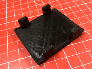
Active Fuse Tester v1.02 3D Printed Base
The printing is a little rough on my own machine, and the fingers that hold the board are a little stiff, but it works. I found it best to slide the board in from one side and center manually.
Active Fuse Tester v1.02 Base Fitted
For those with the equipment who would like to try it out, here are the .STL and .GCODE files.
I have included the .STL file so that users can set their own settings in slicing software. I found that I required a raft for successful printing on my 3D Printer as it is set up at the moment (Anet A8).